| This post discusses about how to use UML models and diagrams in Visual Studio 2010 ultimate edition. Models are very useful to describe the requirements and design of the system. Models help you to visualize how system works and clarifies the user needs and finds the architecture of the system. |
|
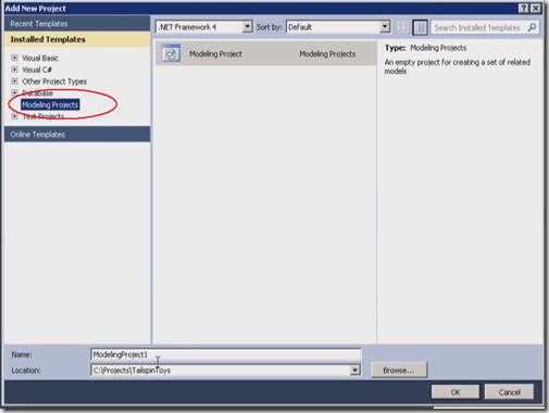
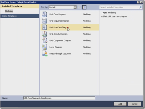
1. Launch the Visual Studio 2010 and create a new project by selecting the modeling from templates window as shown below
2. In this empty project , you will find an empty .uml file which is an xml document which holds all the UML elements
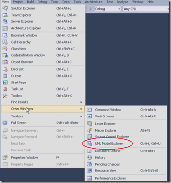
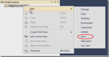
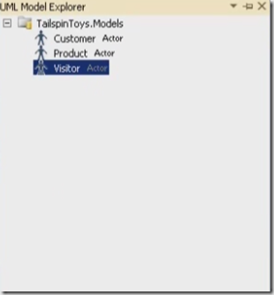
3.Open the UML model viewer from View –> Otherwindows, right click on the root node and add one or more items to this model. In this example I am adding an actor to the model say Visitor and add few more actors customer and product as shown below. Actor just represent the classes of people, organisations or represent software devices which interact with system or sub systems. You can add the description to each actor in properties window.
4. We can also add use cases here, In this example I am adding Browses as an usecase. Now we can add diagrams to this model let us add an usecase diagram as shown below
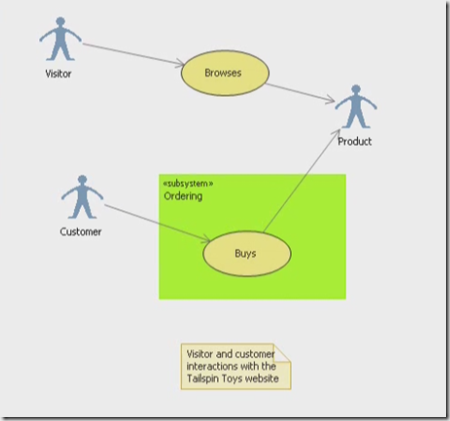
5.It is blank diagram when you create but you can add the actors and usecase that we created earlier to this diagram as shown below. Drag the visitor and customer actors on the left hand side and product on right hand side, in-between add the Browses usecase. Now go to the toolbox and the associations , I am using basic association where visitor browses the product. Now I am adding a subsystem between customer and product named Ordering subsystem which contains a new usecase named buys. Let us put an association between customer and product like customer buys product. You can also add the comments to the diagram which you have created.
6.Notice that all elements which you added to the diagram are automatically appear in model explorer. There is no difference between adding the items to the explorer first and drag to the diagram and adding directly to the diagram.
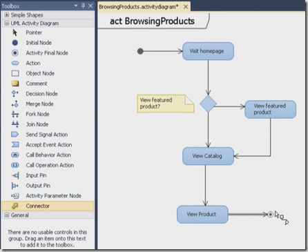
7. Let us add an activity diagram to the model , Activity diagram basically shows business process or software process as a flow of work through series of actions. It is like a flow chart. Add a initial node and an action name it like visit home page and put a decision node under this and called view feature product. Add few more actions as shown below. Add a final activity node as well, use the connector to connect these actions.
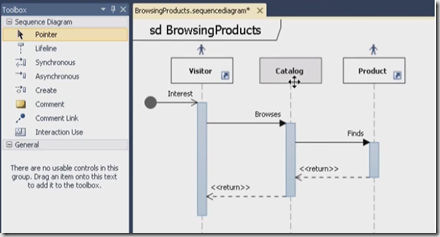
8. Now look at the sequence diagram named browsing products. Sequence diagram shows the interactions which represents the sequence of messages between classes or components, systems or actors. Time flows down the diagram and you can see the message flow from start to end.
9.The typical items in sequence diagram are life lines and messages. In sequence diagram we need say where we begin, usually you can represent asynchronous message when you do not know when it is going to start. Sequence diagrams are very useful to explain the technical steps to non-technical user.
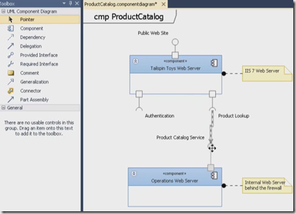
10.Now let us try to add the component diagram to the model. Component diagram basically shows the parts of the design and software system. It helps you to visualise the high-level system and service behavior. In this example the components are web servers. One is a public web server and other one say an internal server for operations. Components are going to have interfaces. Types of interfaces are provider interface and required interface. This is just an high-level view of component diagram which tells how our servers going to talk each other. You can add life line to the component diagram , which automatically adds to the sequence diagram.
This post is to give just an overview of creating UML diagrams. More useful links to learn more about UML in VS 2010 are
http://msdn.microsoft.com/en-us/vstudio/ff655021.aspx
http://msdn.microsoft.com/en-us/architecture/ff476944.aspx
| Share this post : |  |
 |
 |
 |
 |

[…] how system works and clarifies the user needs and finds the architecture of the system…. Read more… Categories: .NET Architecture Share | Related […]
Thanks this info was really helpful! I used a website called Lucidchart to create my own component diagram and it was really easy to understand. If you use diagrams often you should check it out!